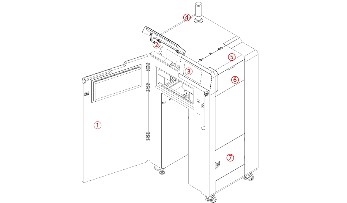
¶ Front and Side
| No. | Name | Description |
|---|---|---|
| 1 | Printer Front Door | Enclosed printing chamber, maintains a constant temperature and airtightness. |
| 2 | Maintenance Window | Includes an IR sensor, USB port, nitrogen flow valve, and card reader. |
| 3 | Touchscreen | LCD capacitive touchscreen serves as the printer's primary user interface. |
| 4 | Tower Light (With Buzzer) | Indicates the device's current operating status: Normal (green); Operational instructions or warnings (yellow); Abnormal (red). |
| 5 | Hopper Lid | Prevents foreign matter from entering and powder spillage. |
| 6 | Hopper | Used for adding and storing printing powder. |
| 7 | Filter Cabinet Door | For inspecting the air intake and exhaust filters. |
¶ Front

| No. | Name | Description |
|---|---|---|
| 8 | Card Reader | Reads powder quota and authorization card. |
| 9 | Nitrigren Flow Valve | Adjusts nitrogen flow. |
| 10 | USB Port | Connects a USB device. |
| 11 | IR Sensor | Measures and monitors the temperature of the printed powder surface. |
| 12 | E-Stop | Restarts the device when it is off; presses to immediately stop the device while it is in operation. |
| 13 | Optical Window | Protects the optical system from contamination during printing. |
| 14 | Powder Bed Surface | Used as the powder bed surface for printing. |
| 15 | Printing Chamber | Stores the Build Unit 220. |
| 16 | Build Unit Connector | Connects the Build Unit 220. |
| 17 | Foot Support | 4, for balancing the device to prevent slippage and vibration. |
| 18 | Caster | 4, for convenient and quick movement of the device. |
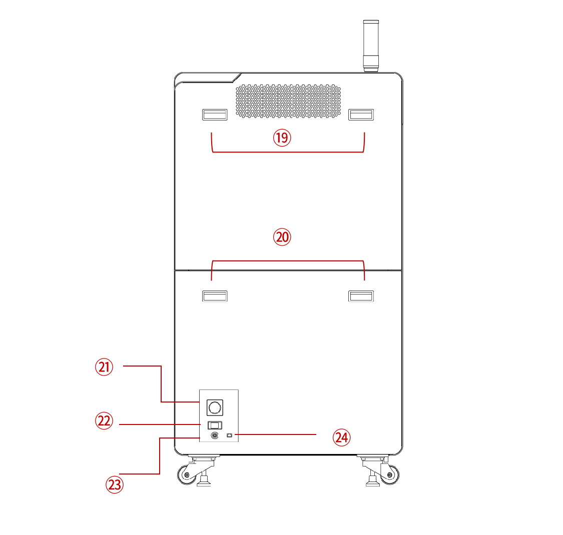
¶ Back
| No. | Name | Description |
|---|---|---|
| 19 | Handles | Remove the upper rear cover for easy maintenance and inspection. |
| 20 | Handles | Remove the lower rear cover for easy maintenance and inspection. |
| 21 | Power Switch | Power the machine on and off. |
| 22 | Power Interface | Connect the power cord. |
| 23 | Gas Inlet | Connect an external compressed air or nitrogen source. |
| 24 | Ethernet Port | Connect a wired network. |