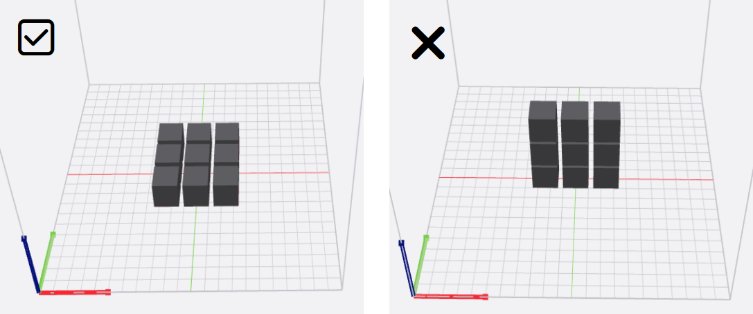
As with all branches of 3D printing technology, the quality of SLS prints is closely related to the initial design. We have summarized some experience regarding model design and arrangement methods. Before printing, please refer to the following design guidelines to ensure you obtain a product that meets your expectations. For model features or arrangements not covered in these guidelines, please contact after-sales service if you encounter printing problems.
¶ 1.Thin Wall
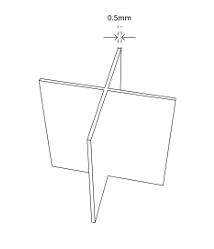
For PANEXT materials, a larger wall thickness helps to form a robust, solid surface, while a smaller wall thickness allows for a certain degree of elastic deformation. Considering the material's inherent strength and toughness, we recommend a minimum wall thickness of 0.5 mm; if it is lower than this value, the parts are prone to breakage during removal and post-processing, making it difficult to maintain structural integrity.
When laying out thin-walled features in ideaMaker, it is recommended to place them in the XY plane (as shown in the figure) to obtain a more balanced dimensional accuracy and overall performance.
When the wall thickness is less than twice the contour compensation (generally for thin walls less than 0.4mm thick), the thin wall parameter needs to be enabled to avoid the loss of thin wall features during scanning. Within the standard template, to avoid excessively sharp corners that could easily result in uneven notches during sandblasting, this function is disabled by default.
¶ 2.Small-sized Thin Wall
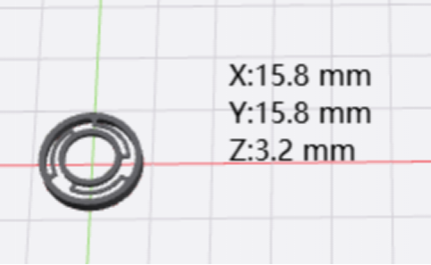
When the model is a small, thin-walled part (Z-axis dimension less than 5mm), as shown in the figure below, the bottom surface of the part is prone to sinking, leading to an increase in the Z-axis dimension. The current effective strategy is to reduce the bottom surface of the model by approximately 0.2mm.
¶ 3.Small Hole
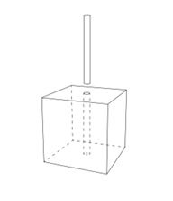
The powder inside the small holes remains at a high temperature during printing, which may cause the holes to shrink or even become completely blocked. For PANEXT material, we recommend a minimum hole diameter of 1mm. Furthermore, for longer through holes, we suggest appropriately increasing the hole diameter during the design phase; while for deeper blind holes or curved internal channels, the diameter needs to be further increased to ensure effective powder removal. For models with complex pore structures, please contact our after-sales team in advance to confirm printing feasibility.
When designing a pin that mates with a small hole, special attention must be paid to the tolerance of the circle (i.e., the number of sides). Excessive tolerance will cause the circle to approach a polygon, resulting in poor fit between the pin and the hole; insufficient tolerance will increase the number of scanning inflection points on the outer wall, relatively increasing the energy density, which in turn will lead to a smaller hole diameter and a larger cylinder size.
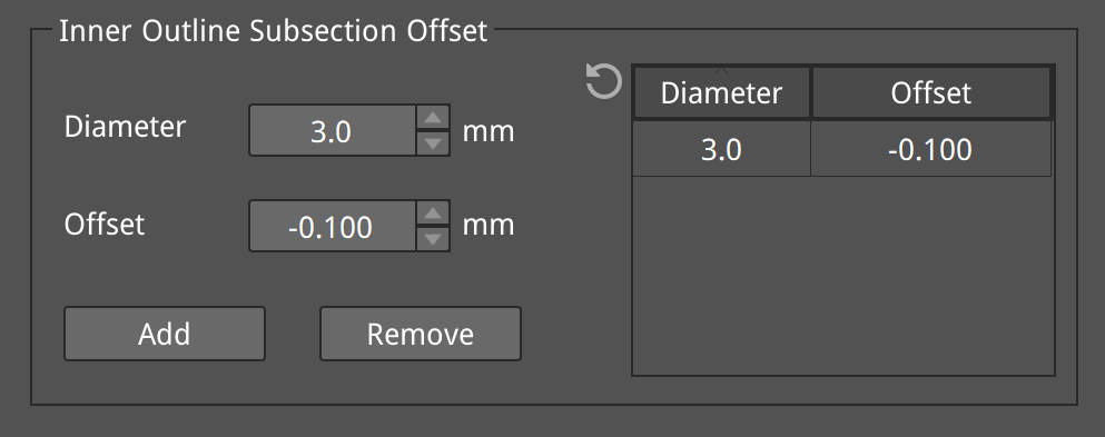
If the inner diameter of a circular hole is too small, but the outer diameter/wall thickness is normal, the inner contour compensation function can be enabled.
¶ 4.Entity
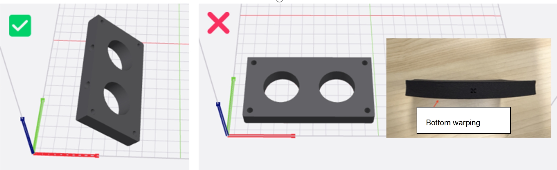
When the model is a solid part/large part (Z-axis solid dimension greater than 10mm), as shown in the figure below, the bottom surface of the part is prone to warping. The most effective measure to deal with this is to tilt the model at an angle of 20°-70°.
For large solid parts exceeding 100mm in any dimension (any model exceeding 100mm in any direction falls into this category), we recommend using a shell design before printing. This significantly reduces printing time and powder consumption, while also preventing deformation of the part during shrinkage. The shell wall thickness is generally recommended to be kept within 5mm.
If a part requires high rigidity or compressive strength, a completely hollow structure may result in insufficient strength. Therefore, internal support structures such as lattices and reinforcing ribs can be designed to improve overall strength without hindering the removal of internal powder. Alternatively, the shell can be completely sealed, utilizing the residual powder inside for support.
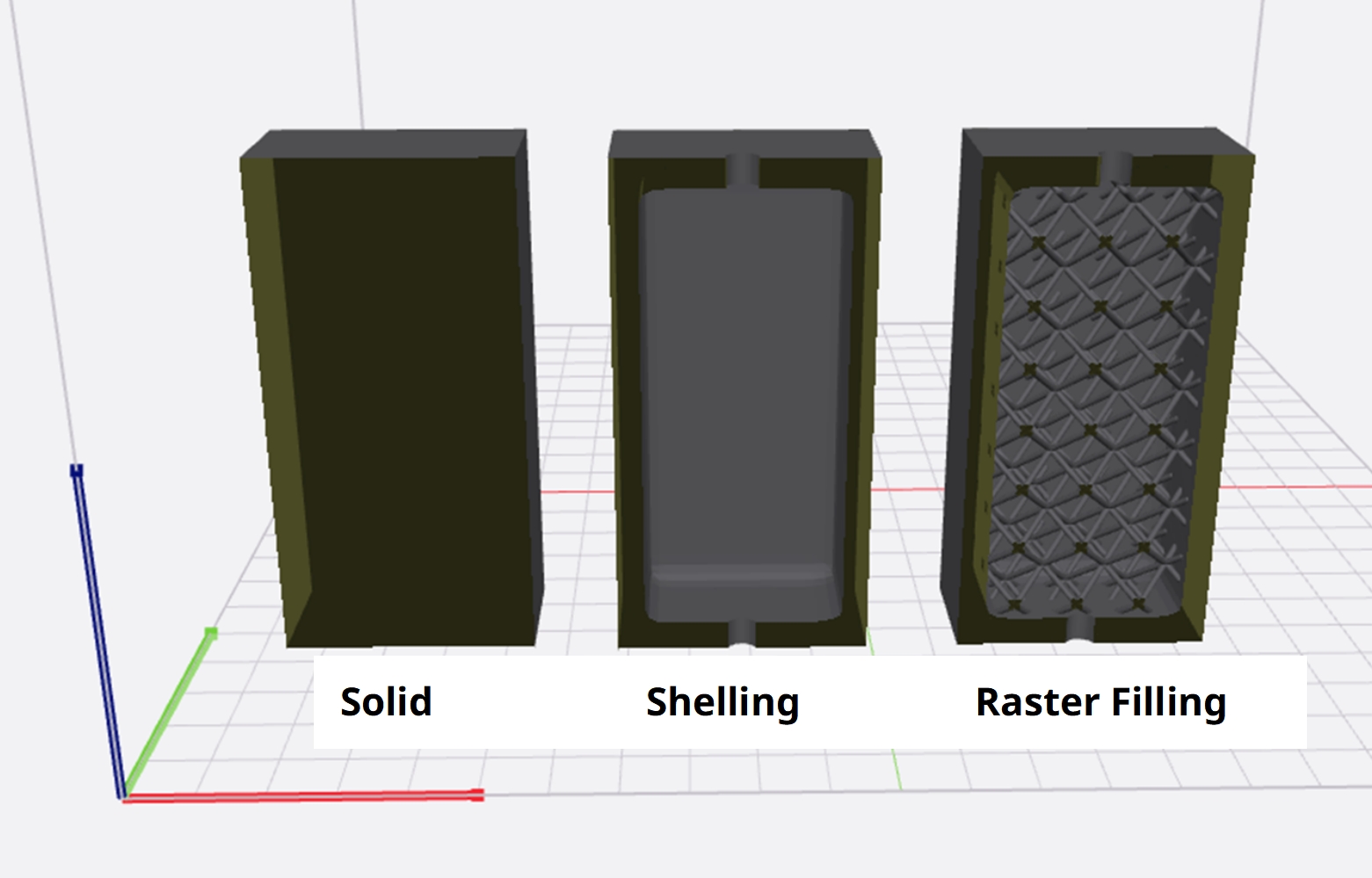
For large shelled parts without special strength requirements, powder removal holes with a minimum size of 5mm should be provided on the shell. It is recommended to have at least one hole at each end of the longest side of the part to facilitate airflow during sandblasting; if the internal structure is complex, the number of holes should be increased. Finally, if the holes need to be sealed after powder removal to maintain a clean appearance, the powder removal holes can be designed as countersunk holes, and matching plugs can be printed for sealing through heat treatment or chemical treatment.
¶ 5.Model Layout
5.1 Detailed Features
For fine features such as small fonts or textures, the order of print sharpness from highest to lowest is: top surface > vertical side surface > bottom surface > upper slope surface > lower slope surface. If the feature is on a slope, it is recommended to maintain an angle greater than 45 degrees with the horizontal direction to avoid creating dense layering.
¶ 5.2 Curved Surface
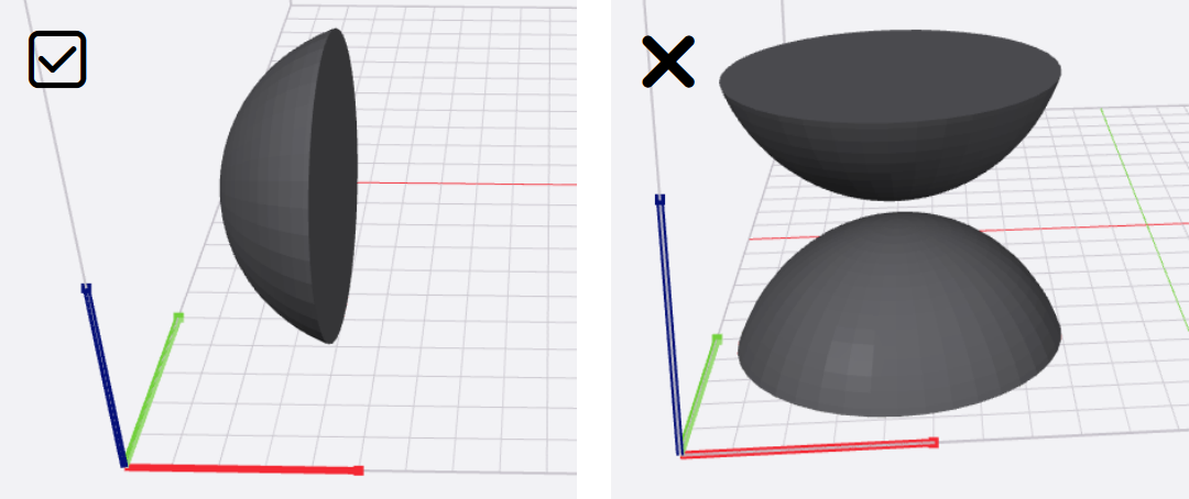
For gently curved surfaces, facing the side can prevent the formation of dense, stepped textures .
¶ 5.3 Large flat surface (flat surface >= 10cm * 10cm)
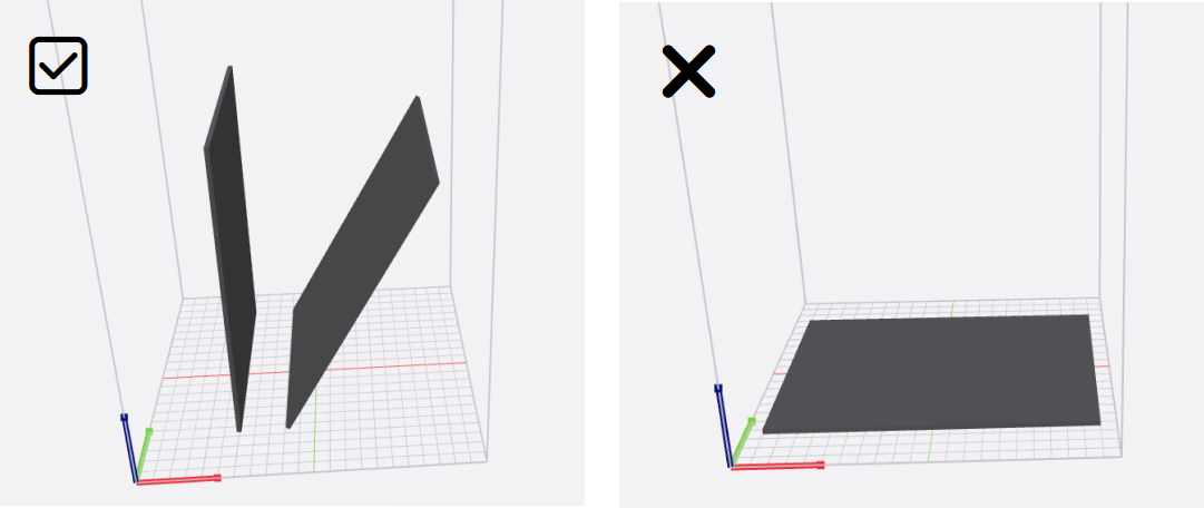
For large flat surfaces, it is generally recommended to place them at an angle or vertically. Horizontal large surfaces may warp during printing. If a smoother surface is desired, it is recommended to place them horizontally at the top of the printing cylinder. For flat plates with a large specific surface area, significant deformation will occur during cooling and shrinkage. Supports can be added (here, support refers to the fact that when placed at an angle, more unsintered powder provides more support) to resist internal stress. Heat treatment can also be used to eliminate internal stress and thus improve deformation.
¶ 5.4 Assembly
To ensure assembly accuracy, it is recommended to reserve a minimum gap of 0.3mm in the assembly structure. When arranging the model, try to keep the structures that need to be matched at the same angle to avoid poor assembly caused by different errors in different directions.
¶ 5.5 Model Spacing
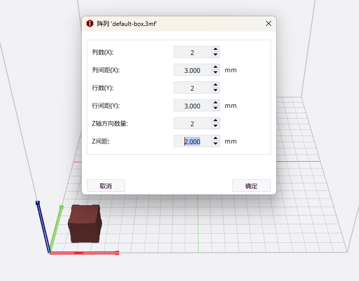
When arranging models in batches, a minimum spacing of 3mm should be reserved. For two parallel surfaces, a larger spacing is required depending on the area size (the spacing between two surfaces larger than 10*10cm should be greater than 5mm) to avoid deformation caused by mutual thermal influence.
Compared to PA12, TPU material shrinks significantly during sintering, and large horizontal surfaces may warp during printing. For large flat surfaces, it is generally recommended to place them at an angle or vertically. For flat plates with a large specific surface area, significant deformation will occur during cooling and shrinkage. Adding supports can help resist internal stress, and heat treatment can also be used to eliminate internal stress and improve deformation.
¶ 5.6 Small-sized parts
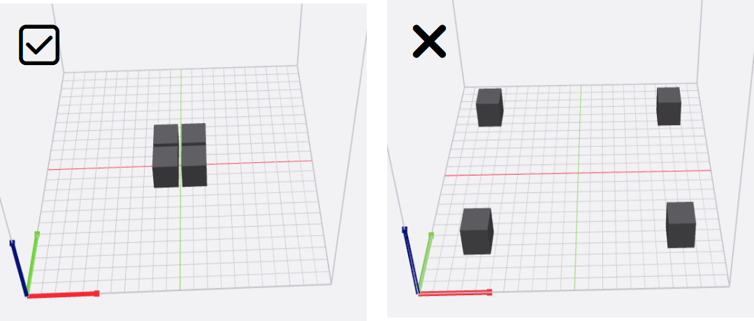
When arranging small-sized parts (cross-sectional area ≤ 1cm³), please place them in the center as much as possible. Since the bonding force between the small molten pool and the powder bed is weak, placing them on the edge may cause defects such as warping and ejection.
¶ 5.7 Saves time and materials
When printing non-flat parts, please place the parts flat on the printing surface as much as possible to reduce the printing height and shorten the printing time and material usage.